Hangar Door
Moderators: GAHorn, Karl Towle, Bruce Fenstermacher
-
4-Shipp
- Posts: 434
- Joined: Mon Apr 22, 2002 11:31 pm
Hangar Door
Anyone out there with construction experience? I need some engineering advice.
I am getting ready to put rolling doors in the end of my barn to make it a hangar. I need to poor a concrete foundation for the roller tracks. it will be about 8" wide and 60 feet long. My question is how deep should it be?
There will be two doors, each 20' wide that will double up off the end of the hangar when open. The track will be 60' in length. I am in north Texas and we don't get many freezes so I was thinking 12-18 inches deep. Obviously the shalower the better - easier to dig and less material.
Thanks.
Bruce
Bruce Shipp
former owners of N49CP, '53 C170B
former owners of N49CP, '53 C170B
- flat country pilot
- Posts: 230
- Joined: Thu Mar 16, 2006 1:46 pm
Bruce,
I am not going to give you any hard numbers without looking at your location, soil, water movement, weather data, intended use, etc… Is this door going on your red steel building? What is the soil type and characteristics? Does the ground move? How high is the water table and does it move? What is your average and peak wind velocity and from what direction? What else will you drive across this footing?
Pour the footing at least 12†by 12†and use rebar. You should have a minimum of four rebar evenly spaced the entire length. Don’t take a short cut with wire mesh or rely on a fiber mix. If you ever drive a large tractor, pay loader, or tracked dozer in there, you will want 12†by 24â€. Your question is how deep should it be? Minimum 12†by 12†and rebar. I don’t like 8†by 60’ long.
If you are going to roll your doors on the ground, consider small rubber pneumatic tires. But you will need a support structure and track at the top. Therefore consider hanging the doors from the top. If you hang your doors from the top, you only need a footing across the opening in the building and the hardware lets you adjust door height if the ground moves. You will want a guide at the bottom so the doors don’t swing in the wind.
Either way, never let the wind catch you with your doors open. We designed a building with tracked doors that opened on a 60’ track very similar to what you are describing. We had posts set back at 90 degrees to brace the track structure against the wind. No warranty and no guarantees. He did not build it.
I do know a farmer who has double hung sliding doors for his airplane. He lost the whole set up last year in a 100 mph wind. Doors came off, building pulled out of the ground, Cherokee 180 to the bone yard. He replaced the building and put the same type of doors on but turned the structure a different direction. We’ll see, time will tell.
I built my bi-fold door for about $1,400. Steel, bearings, drive motor and gear box, light machining. That is everything except my time. If you can measure, cut steel and weld, go with a bi fold. Looking at your pictures your house is close enough to run electricity to you hangar. You only need 120 volts and a ¾ hp motor.
If you want to consider building a bi fold door, I will take detailed pictures of mine for you. It is 40’ wide and I forget the height right now, loss of memory due to age I think.
My door went through the same 100 mph wind storm and stood very well, no damage. Several buildings, barns and one entire town went to the ground in that storm. I have confidence in my door, but was also very lucky.
Bill
Flat Country Pilot
Farm Field PVT
54 C170B
Farm Field PVT
54 C170B
-
john rogers
- Posts: 20
- Joined: Thu Dec 09, 2004 3:32 am
- 170C
- Posts: 3182
- Joined: Tue May 06, 2003 11:59 am
Hangar Doors
Bruce, I am not an engineer either, but did put in a concrete floor (4-6"), walls & doors in what was an end hangar in a row of T Hangars several yrs ago just West of Fort Worth. As others have suggested, be sure the concrete base is sufficient to handle anything you would likely ever drive into that barn/hangar. Some extra $$ spent now could save a lot of problems later. I would go deep enough to get to something solid if that is realistic since a lot of soils here in TX tend to be clay in composition and have resulting shrinkage/expansion problems. Probably not as much of a problem on your door threshold as it is on the floor of your hangar. I'd ck with some of the old timers in Iowa Park, Burkburnet and WF to see if those problems are common to that area. Sliding doors are OK and do have some advantages over bi-fold doors. Less structure needed to support them, etc., but if I were building again I would do my best to use the bi-fold method. When those rolling or sliding doors are open they sure are suspetible to winds and from personal experience/knowledge, you live in an area quite prone to high winds. Personally I like the bi-fold that uses the 4"-6" wide nylon or similiar staps to lift the door vs the cables. Even if you build the door youself or have it done I think you can purchase the strap material in vrs area's. Who knows, there might even be some suplus webbing at Sheppard you could get.
Good luck.
Good luck.
OLE POKEY
170C
Director:
2012-2018
170C
Director:
2012-2018
- GAHorn
- Posts: 21231
- Joined: Fri Apr 12, 2002 8:45 pm
Bruce, when I chose to build my own hangar door I looked at tracked doors such as you are considering, bi-bolds, and hydroswing, and gave up on all of them due to their mutual problems of winds. Even bifolds do not do well if left open in a wind.... they collapse upon themselves.
And what was another problem I had with bifold was the loss of headroom. (I realize that the header can be mounted higher up on some bldg designs and alleviate some of the headroom losses, but still not as much as I'd like, so I designed my own door, fabricated and installed it.)
I'll send you some pics. It's 14' X 44' and is impervious to any winds the bldg itself will withstand. (Design was 120 mph.) The door can be operated in winds, left open or closed without harm to the door. (Of course, my clear-span hangar faces South and therefore is not likely to "inflate" with frontal winds.) The door was built of 2X6 retangular tubing and skinned with common R-panel. It weighs only 1700 lbs and needs very little internal bldg structure to support it. When open, it lies horizontal with half inside, and half outside the bldg, forming an awning.
I used a common 110 volt boat-lift to raise/lower my door. This has the added advantage of no need for a brake or other machinery to stop the door at any degree of movement, yet it will remain where stopped. Full 0pen or Full Closed takes about 2 and a half minutes. My total costs were also less than $1500 for mat'ls. My cousin and I welded/fabricated the majority of it ourselves over a weekend, even with Ol' Gar's constant harrassment. It was completed over a subsequent weekend and insulated/skinned on one more.
And what was another problem I had with bifold was the loss of headroom. (I realize that the header can be mounted higher up on some bldg designs and alleviate some of the headroom losses, but still not as much as I'd like, so I designed my own door, fabricated and installed it.)
I'll send you some pics. It's 14' X 44' and is impervious to any winds the bldg itself will withstand. (Design was 120 mph.) The door can be operated in winds, left open or closed without harm to the door. (Of course, my clear-span hangar faces South and therefore is not likely to "inflate" with frontal winds.) The door was built of 2X6 retangular tubing and skinned with common R-panel. It weighs only 1700 lbs and needs very little internal bldg structure to support it. When open, it lies horizontal with half inside, and half outside the bldg, forming an awning.
I used a common 110 volt boat-lift to raise/lower my door. This has the added advantage of no need for a brake or other machinery to stop the door at any degree of movement, yet it will remain where stopped. Full 0pen or Full Closed takes about 2 and a half minutes. My total costs were also less than $1500 for mat'ls. My cousin and I welded/fabricated the majority of it ourselves over a weekend, even with Ol' Gar's constant harrassment.
'53 B-model N146YS SN:25713
50th Anniversary of Flight Model. Winner-Best Original 170B, 100th Anniversary of Flight Convention.
An originality nut (mostly) for the right reasons.
50th Anniversary of Flight Model. Winner-Best Original 170B, 100th Anniversary of Flight Convention.
An originality nut (mostly) for the right reasons.
-
sphillips
- Posts: 104
- Joined: Sat Dec 24, 2005 2:33 pm
- GAHorn
- Posts: 21231
- Joined: Fri Apr 12, 2002 8:45 pm
Another way to increase stability is to drill/augur 9-12" holes down 3-4' at each end (and maybe the middle) of your support foundation. Place rebar vertically into the holes, and tie it to the horizontal rebar along your track-foundation. This will provide deep piers/footing for your track foundation.
'53 B-model N146YS SN:25713
50th Anniversary of Flight Model. Winner-Best Original 170B, 100th Anniversary of Flight Convention.
An originality nut (mostly) for the right reasons.
50th Anniversary of Flight Model. Winner-Best Original 170B, 100th Anniversary of Flight Convention.
An originality nut (mostly) for the right reasons.
- 170C
- Posts: 3182
- Joined: Tue May 06, 2003 11:59 am
-
bsdunek
- Posts: 425
- Joined: Wed Feb 11, 2004 6:42 pm
All the advice is good, but I think this is most important! Here in Michigan, I consider four feet minimum depth for any kind of foundation. We get frost to more than three feet in a cold winter. You need to consider how deep frost can go in your area and go a foot deeper.sphillips wrote:You need to find out what theh frost line minimum depth is for your area. You dont want the frozen soil to heave the concrete , which it will. So, it may require a spread footing with stemwall to get below frost line. Check with your local building dept about minimum depth.
I also might recommend you contact your building department to see what their footing depth recommendations are.
Bruce
1950 170A N5559C
1950 170A N5559C
- 3958v
- Posts: 545
- Joined: Tue Apr 23, 2002 12:00 am
Bruce Here comes advice from an excavation contractor for over 25 years. Find out how deep your deepest frost depths are in your area and go an extra 6" to a foot on the North side on the South side the deepest frost depth will give you plenty of protection. If you are planing on renting a machine to do it yourself don't bother unless you just want to play for the day. If you can find a small local contractor guy who will work by the hour he will cost you less money and probably do a better job. Digging with a backhoe is like landing an airplane no matter how smart you are its going to take you a little to get good. Hoefully you don't need to get a permit. Bill K
Polished 48 170 Cat 22 JD 620 & Pug
-
4-Shipp
- Posts: 434
- Joined: Mon Apr 22, 2002 11:31 pm
Wow! All great info.
Two others have built similar rolling doors in the last two years and I am happy with the cost, simplicity and ease of operations of their doors. I have considered putting the rollers on the top versus the bottom but I have been very impressed with the results the other two have had and I have had many challenges with hung doors in other hangars.
The doors will open over the end of the building that has a 12 ' lean-too so there will actually only be 8' of door extended past the main structure when fully opened. The barn was professionally built -welded from 3 and 4 inch steel pipe-and has held up well against our North Texas storms - both winter and summer! Having the doors blow off the tracks is a concern that will have to be addressed accordingly!
I also had not considered the effect of driving heavier equipment across the door. There is a concrete apron in front of the existing 16' overhead door that is currently on one end of the proposed opening.
Here in Wichita Falls we rarely get the ponds to ice over so a hard freeze is not a concern. However I did not consider the impact of driving other equipment over the entrance.
I think I need to get some professional advice before I proceed too far, as you all have brought up several points I had not considered. Thanks!
Bruce Shipp
former owners of N49CP, '53 C170B
former owners of N49CP, '53 C170B
- GAHorn
- Posts: 21231
- Joined: Fri Apr 12, 2002 8:45 pm
Re: Hangar Doors
…170C wrote:George, share your photos with all of us.
OK, but this is before I finished completely and got the area picked up.
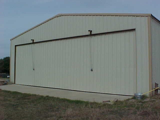
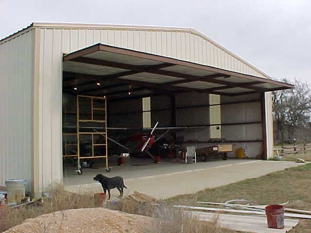
Outside View. Door measures 14' X 44'. The door is not actually resting on the concrete. It is suspended on two axles/steel-wheels at each end, mounted slightly above the midpoint of the door-ends. They are captive in a track built into the hangar-frame. (The hangar opening is framed by 10" flange beam (I-beam.) This means the door is free to pivot as it is lifted. The door structure is predominantly made of 2"X6" steel rectangular tubing. 3" square tubing protrudes thru the header of the bldg and has 3 sheaves (pulleys) on the outer end for the operating cables. That 3" sq. tube is about 9 ft long, most of it inside as you'll see, and it is resting on an 10" beam which makes the header across the top of the door opening. The 3" tubing provides a mounting surface for the 3 pairs of sheaves inside that take the cable from the spindle, and turn it outward so it can exit thru the header, over the outer 3 pairs/sheaves and down to the door's pickup points.
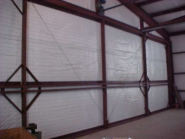
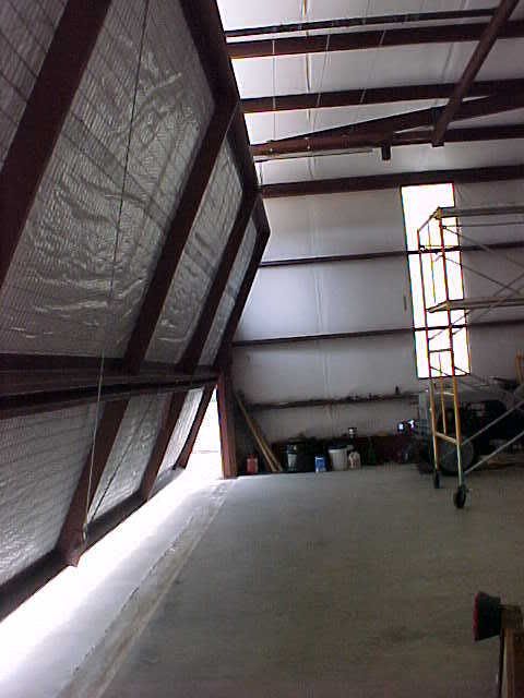
Inside View. The two "diamonds" are made of 2" angle and are used to surround and stiffen the inside area of the cable pickup points. Notice the pick-up points are between dual 2"X6" rect. tubing. These act like a wing-spar to prevent the door from bending or sagging when fully open. (Also, the door is 44' wide and is being picked up 11' in from each end, so each pickup point is actually a balanced 22' span. This door couldn't sag if it wanted to.)
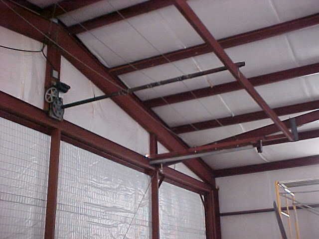
Boat Lift, Spindle (2" X 10' black-iron pipe), and supports for horizontal sheaves. A 1/2 hp electric motor spins a worm gear, which turns a ring-gear, thru which that spindle (2" pipe) is mounted. The spindle is thereby twisted, wrapping the cables about the pipe and thru a system of sheaves (pulleys) pull the door progressively upward and the top of the door inward. Since the (3) cables pass thru the spindle and are counter-wound around it, the stress of lifting the door is completely opposed by itself,...there is no strain at all on the pipe. The end of the pipe opposite the lift is actually free-floating within a light stanchion made of 2-1/4" pipe welded atop the 2X6 rect. tube. Smeared a little grease inside to prevent sqeaking sounds. The door goes up/down almost silently except for the whirring of that 1/2 hp electric motor. (Uses 12 amps.)
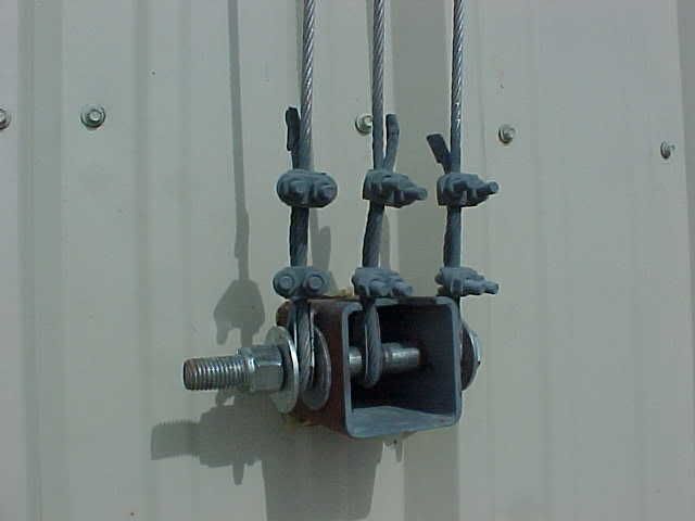
Cable attach points outside view. This point is about 14 inches below the center of the door to provide for tipping the top inwards into the hangar prior to any actual lifting of the door. This is made up of 3" sq. tubing and a grade 5 bolt, etc. The cut ends of the cable were sealed with JB Weld (epoxy) to preclude fraying, then all the hardware was sprayed with cold-galvanize zinc-rich paint to prevent rusting. The opening thru which this 3" tubing passes was then sealed with 50-year RTV to prevent water from getting thru to the insulation, especially when the door was up/open. The inside end of the 3" sq. tubing was closed off by welding a flat plate across it, tying the two spars together also. (Didn't want to give mud daubers a free ride into the hangar with an open 3" tunnel.)
Inside view closeup of "spar" at the center of the door. This piece of 3" sq. tube does not penetrate thru the door, but is only used as a spacer for the spar. (That's why I didn't need to weld a plate across it or close it off....no daubers can get thru here!)
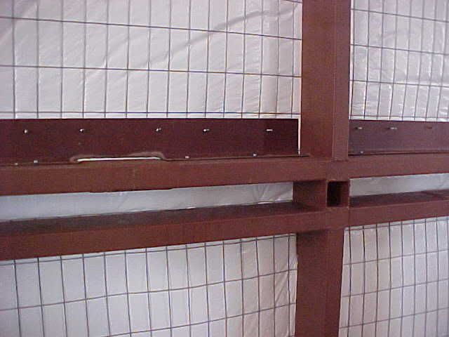
Cables exit and go over sheaves down to outside attach point. (These are actually grade 8 bolts because I already had them in stock. Grade 5 would be fine. I lubricate the bolts/sheaves once a year with waterproof boat-trailer wheel bearing grease. 4 years and several hundred operations show negligible wear. I got bored one day and drilled all the sheave-bolts lengthwise from the head down the centers and then crosswise where the sheaves ride, and tapped/installed a grease-zerk-fitting in the bolt-head so I could just shoot a dab of grease in there and not have to disassemble. Not necessary, but I was bored and having fun. This is really a low-stess useage.) That lower/vertical piece of 3" tubing was later cut off (it was originally intended for additional closing mechanism which proved unnecessary) and a sheet-metal rainproof box or bird-house was constructed from matching R-panel to protect this entire sheave and cable assembly from rain. If I can remember to take a pic of it, I'll post it also.

The door begins to open...first the top tips into the hangar, and then as the cables continue to wrap around the spindle, the top of the door is supported by chains and trolley-tracks, preventing it from falling into the hangar. Look very carefully at the top of the door just above the third upright-frame from you and you'll see the chain which is welded to the top frame of the door and the other end attached to the track-trolleys.
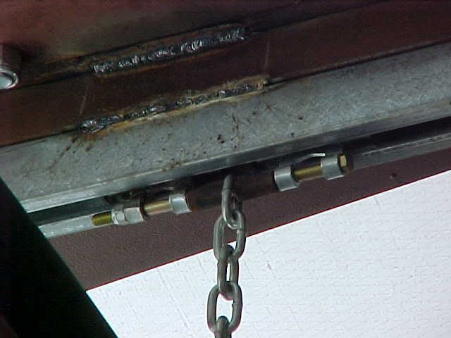
Here's a close-up of the track trolleys. Note that the top of the door is supported by two captive track-trolley systems, one above each main cable pickup point. The top of the door is suspended by those flexible chains. Designed for lightweight hanging/slider barn doors, I bought them at Tractor Supply. I used two tracks, and four trolleys (two trolleys are connected by a 3/8" X 8" bolt which passes thru the chain.):
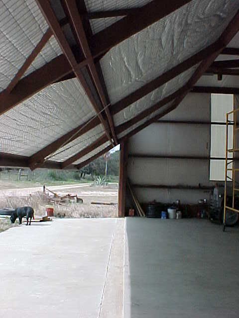
The door continues to open. The cables are lifting it from the pickup points at the spar, and the top of the door is being supported by the chains/trolley-tracks. (The boat lift/door can actually be stopped at any place along it's travel and it will remain in that position. No brake is required due to the worm/ring gear arrangement of the boat-lift.)
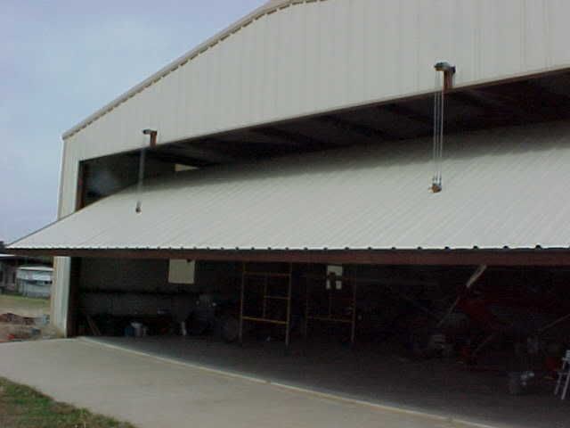
Fully open it steals only 8 inches of headroom and is absolutely unaffected by wind in any position, either fully or partially open because the ends of the door is secured within a track made up of two 6" steel wheels captured within I-beam and angle. The wheels are mounted 8" above the center ends, so the door at rest is bottom heavy and remains closed naturally, even against strong winds. When the door is fully closed, it is resting on those wheels in the lowest part of the end-tracks...the door is not actually resting on the slab. That's why it pivots open so easily when lifted by the calbes, clearing the door header before any portion of the door raises.
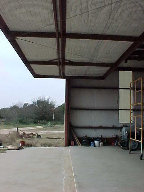
Since the door is 14' tall, and is pivoting horizontally as it is lifted, only 7' of cable needs to be wound up on the spindle to bring the door fully open. 2" pipe has an outer diameter of slightly more than 6", so only 14 turns of the pipe will fully open the door. (The door only needs to move up 7' to be fully open.) From fully closed to fully open takes less than 3 minutes. It could be speeded up by using 2-1/2" pipe for a spindle with no problem but I'm OK with the speed as it is. (Gives me time to kick the chocks, pull the covers, etc.) Fully open, about 8' of door is overhead inside the hangar and 6' outside, providing a short awning effect. (Kinda fun to sit out in the hangar when it's raining and drink a beer. All the water hits the apron outside the doorway.)
The major matl's used were:
3" square tubing (3/16" wall) one 25' stick
2" X 6" rectangular tubing (11 ga.) 6 (six) 40' sticks.
12 5" steel sheaves
160' 7X19 stainless aircraft cable(7,000 lb rated), thimbles, clamps.
5/8" grade 5 bolts for sheaves (six were 5" long, four were 8" long)
Ny-Lok Nuts and large flat washers
Fiberglass insulation (one roll, 6' X 150')
2"X4" grid, goat-wire fencing, 60" wide X 150' long to support insulation. (3 rolls)
8" X 11 lb flange-beam for header support and end tracks. (2 X 25')
2" square tubing to suspend roller tracks from 3" sq. tubing sheave supports. (1 X 20')
Two 6" steel wheels and 3/4"X 8" grade 8 bolts/nuts for door end-support at rest and to capture door ends within vertical track made up of left-over 8" flange beam and left-over 4" angle.
Track and trolleys for upper door support and chain, 3/8"X 8" bolts. (20' of track)
4"X4" angle for general support and to suspend 3" sq. tubing from beams. (one 20' stick)
115 volt boat lift rated single-pull at 4800 lbs. (door weighs 1700 approx)
2" pipe, 10 ft long for spindle, and pipe stanchion to capture end opposite boat lift. (The boat lift supplier can help with all hdw related to the lift.)
14 ga. "R" panel in 3' widths, 14' high (15 panels)
2"X4" base-angle to provide for attaching the R-panel to the rect. tubing. (5 sticks, 20' long)
Neoprene washer metalscrews for R-panel and base-angle.
2"X2"X36" angle for stiffeners at corners and cable pickups. Probably completely unnecessary after sheet metal is installed. It was probably overkill. (16 each)
3/8" galv. cable for strain relief of lower center of door to prevent anticipated sagging (The apron of the hangar was not exactly poured level and was about 1/2" higher in the center than at the ends. The cable was anticipated necessary in order to guarantee the door would not drag on the apron on opening/closing...proved unnecessary, especially after the sheet metal was installed. More overkill.)
Weather seals are made of black EPDM 14" wide and the appropriate length (either 44' for top/bottom, or 14' for ends of door), folded in half so it formed a loop, and stapled to itself. It was then slipped beneath the R-panel/J-trim before the panels were screwed completly down. Since the door is surrounded top/ends by 8" flange beam and bottom by the slab, about 2" of the folded weatherseal was left exposed to completely close the door opening against weather and insects. (I hate mud daubers.)
J-shaped trim to finish the edges. (5 sticks X 20')
A sheetmetal screwgun for the R-panel and goatfencing.
With three cables counterwound acting like six cables, the safety factor is quite high, about 42,000 lbs of capability lifting a 2400 lb door. The lift lightly loaded, and the trolleytracks are rated at 600 lbs each, and with two sets of trolleys each giving 1200 lbs of capability. But the balance of the door fully open only places 120 lbs on them.
Probably used about 50 lbs of 7018 welding rod. (6011 or 6013 would probably be OK also, but I had the 7018 low hydrogen (for strength) left-over from building the hangar. The matl's had sat around for two years and was slightly rusty so I used a stick welder on it for penetration. I had two helpers (a cousin who is a professional welder and a goofy guy from Toledo Bend who is a professional goofy) help with most of the heavy construction. A scaffold and a welding machine, mitre/chop saw, and an angle grinder for most of the work. After the framework was all up, I used an angle-grinder with a wire wheel to brush it all off before painting it with Ospho (phosphoric acid) to rust-proof it, then painted it with red-oxide oil-base paint.
Then goofy and George Courtney (NH area rep) came down for Xmas and helped me put on the insulation and screw on the sheet metal in one day. Total time spent actually working was about 10 days.
The black lab is my Roulette! The edge of the concrete is her boundary unless I release her with her secret word. She's a really sweet dog with a desire to please. A real frisbee expert.
'53 B-model N146YS SN:25713
50th Anniversary of Flight Model. Winner-Best Original 170B, 100th Anniversary of Flight Convention.
An originality nut (mostly) for the right reasons.
50th Anniversary of Flight Model. Winner-Best Original 170B, 100th Anniversary of Flight Convention.
An originality nut (mostly) for the right reasons.
- GAHorn
- Posts: 21231
- Joined: Fri Apr 12, 2002 8:45 pm
Re: Hangar Door Foundation
A hazard of the electric door mechanism is that if left unattended while the door is in motion, there is the possibility that the door will reach it's full UP or full DOWN position and the motor continue to run if no one is present to stop the electric motor. This results in the door reaching the end of it's travel...then (if DOWN was the last direction selected) reversing itself as the cables continue to be wound around the spindle in the same direction as their last movement. Whichever direction last selected, if then neglected by the operator, the door will eventually be raised to the point that it can not raise any further and the motor will either stall out and pop it's internal circuit breaker, or (more likely) the drive V-belt will be destroyed. (The door will be in a safe, but full UP position.)
The door really needs limit switches to stop it's movement at either the full UP or full DOWN positions, should the operator become distracted or should he desire to leave the area with the door still in operation.
Here's my solution for limit switches for my hangar door operation.
I simply made another closed-circuit cable-run. It's counter-wound upon the spindle, and kept taut with a heavy spring (from Tractor Supply). CLICK on PICS to ENLARGE. It runs thru two U-bolts welded onto a plate, welded upon a common gate-hinge, which is welded to adjacent structure. The cable reverses direction behind the plate around an idler-pulley/sheave. I placed two common cable-clamps, one each at the appropriate locations on the closed-loop cable, so as to arrive at the hinged-plate when I want the door to stop on opening and closing. The clamp presses against the plate, which presses against two normally-closed switches (School-bus aisle-light switches, wired in series, for safety) which open and interrupt the electric-motor's circuit, which stops the motor when the door is fully open...or fully closed. I mounted them thru perforated angle, and used small tension springs to hold the hinged plate against them so the plate would never move out of position. The two switches (Car Quest PN DS-272, Standard Motor Products PN 532) are wired in series so that even if one should ever fail, the other will also interrupt the motor circuit. The school bus switches are rated at 30 Amps D.C., and therefore are more than sufficient for the 15 Amp A.C. motor. I used a Press-to-Start switch from a junked clothes-dryer to initiate the motor from a stopped position. (Power runs from the main Up/Down selector to the schoolbus switches to the motor, then back to the U/D selector. The dryer press-to-start switch by-passes the schoolbus switches so as to momentarily provide power to the motor, which then turns the spindle moving the limiting cable-clamps away from the hinged plate which, now relaxed, allows the school bus switches to close again. Releasing the dryer switch now re-arms the limit switches again.)
Of course, the main U/D selector can be moved to the stop (middle) position at any time. The door continues to run in the direction selected until the U/D selector is changed, or the limit switches are activated by the cable.
While the arrangement limits the door's operation at the full Up or Down positions, it's important to realize no provision is made to protect an animal or person from a closing door. I expect to place a photo-electric interrupt in place at some point.
IMPORTANT: The cable is wound around the spindle, then passes THRU a hole drilled thru the spindle and is wound around the spindle one more time before proceeding on it's way to the reversing pulley/sheave at the hinged switch-plate. This is to insure that the cable will never slip it's position.
Also, it is planned to add a short "jumper cable" which will loosely connect the ends of the closed-loop cable to each other (passing thru the center of the spring) to guard against that spring ever breaking and letting the mechanism fail.
Anyone needing two limit switches, I bought two spares I'd like to get my $5 each back on. I also have a spare heavy duty cable tension-spring I'd like to get my $8 back on. I'll pay the shipping.
You do not have the required permissions to view the files attached to this post.
'53 B-model N146YS SN:25713
50th Anniversary of Flight Model. Winner-Best Original 170B, 100th Anniversary of Flight Convention.
An originality nut (mostly) for the right reasons.
50th Anniversary of Flight Model. Winner-Best Original 170B, 100th Anniversary of Flight Convention.
An originality nut (mostly) for the right reasons.
- Kyle Wolfe
- Posts: 706
- Joined: Mon Mar 17, 2003 12:30 am
Re: Hangar Door
George, you speaking from experience or were you thinking ahead on this one?
Kyle
54 B N1932C
57 BMW Isetta
Best original 170B - Dearborn, MI 2005
54 B N1932C
57 BMW Isetta
Best original 170B - Dearborn, MI 2005
- GAHorn
- Posts: 21231
- Joined: Fri Apr 12, 2002 8:45 pm
Re: Hangar Door
Both. I had planned from the beginning of the project to invent some sort of limiting device but had yet to visualize how. Until then, the door req'd the operator to stay at the helm and stop the door at whatever position necessary.Kyle Wolfe wrote:George, you speaking from experience or were you thinking ahead on this one?
One day our son came to borrow some tools and while distracted by the telephone allowed the door to continue operation. It resulted in the door fully lowering, then fully raising until it could raise no more. The motor's drive pulley burned thru the V-belt and then began free-spinning. No harm done other than the V-belt, but it required me to spend about an hour lowering the door by manually spinning the driven-pulley, then re-aligning all the cables and replacing the V-belt. A good feature of the boat-lift is that it requires no safety-brake. The worm-gear driving the ring-gear is a natural brake and will hold the door in whatever position exists at the time of failure.

'53 B-model N146YS SN:25713
50th Anniversary of Flight Model. Winner-Best Original 170B, 100th Anniversary of Flight Convention.
An originality nut (mostly) for the right reasons.
50th Anniversary of Flight Model. Winner-Best Original 170B, 100th Anniversary of Flight Convention.
An originality nut (mostly) for the right reasons.
Cessna® is a registered trademark of Textron Aviation, Inc. The International Cessna® 170 Association is an independent owners/operators association dedicated to C170 aircraft and early O-300-powered C172s. We are not affiliated with Cessna® or Textron Aviation, Inc. in any way.