Photos of blast tube placement
Moderators: GAHorn, Karl Towle, Bruce Fenstermacher
-
ghostflyer

- Posts: 1395
- Joined: Mon Apr 21, 2008 3:06 am
Re: Photos of blast tube placement
The weight of the Chiller or heat sink is very light and the large hollow bolt assembly that holds the filter assy is more than adequate to support the fitting . My oil temperature dropped big time and suggest that some air flow or tubulance from the exit air and on coming air helped. Due to the very high ambient temperatures it was some times impossible to fly with a load and climb out to a height where the air temperature was bearable in the cabin . It was very tight when the fins were fitted but gentle positioning it can be done .

Re: Photos of blast tube placement
What are your typical oil temps, with the fins?
Many feel that a minimum of 180 is necessary to avoid excess water buildup.
My FM Enterprises filter, non relocated blast tubes, summer Texas heat....new, calibrated oil temp gauge.....indicates 200 F, even l on blistering days.
In other words, there are a lot of variables and differing causes of high oil temps,.....exhaust leaks, poor baffles, bad gauge, etc
'53 B-model N146YS SN:25713
50th Anniversary of Flight Model. Winner-Best Original 170B, 100th Anniversary of Flight Convention.
An originality nut (mostly) for the right reasons.
50th Anniversary of Flight Model. Winner-Best Original 170B, 100th Anniversary of Flight Convention.
An originality nut (mostly) for the right reasons.
-
ghostflyer
- Posts: 1395
- Joined: Mon Apr 21, 2008 3:06 am
Re: Photos of blast tube placement
My original oil temp gauge is the old style with the green band and has the brand name on the lower edge called "American Standard" and on the right hand lower edge is the word " Rochester" . When flying in the adverse conditions without the spin oil filter and "chiller" it used to quickly settle on the edge of the red and green band. When the spin on oil filter was fitted the temperature dropped to where the indicating hand would cover the "L" on the letter OIL on the gauge . When the heat sink "chiller" was fitted the indicating hand used to sit straight up and down . I tested the gauge and assembles a number of times using boiling water and gauge seemed to indicate correctly . It has a scale of 100 degs to 225 degs F written on the face of the gauge . When I first bought the 170 project the lower cowl had been rebuilt a number of times and the exit hole for the spent cooling air was a lot larger than some of the "original" 170's that I have seen at Oshkosh . The lip was also about 2.5 ins wide also. My baffles and seals were nearly new also and sealed correctly .
Re: Photos of blast tube placement
There are several interesting points in this thread, all of which have been addressed at one time or another in various threads....so just to reiterate a few of them here...
1. The original oil temp gauge range was from 100-225 where there was a red line. Subsequently, TCM revised the engine type cert. data sheet to allow an increase in oil temp to 240-F if single-weight SAE 50 aviation (Milspec) oil is used. The early/original gauge markings may appear distressing, but with that updated info should relax a bit.
2. This engine (C145/O300) has several unique features which may escape the casual observer when compared to other engines in similar service. There is no oil cooler. TCM reviled at the external oil cooler systems used on other brands/designs because of the added weight and hazards of external oil lines. (Lyc. has a history of engine failures due to their use of external, aluminum oil-return lines at the rockers, and oil hoses to remote-mounted oil coolers. I personally prefer the FM and TCM oil filter adaptors which are integral to the accy case and one reason is to stay away from the external lines of the types which remotely mount.) TCM addresses the issues differently (and in my opinion, better) than Lyc and some others. Firstly, no external oil lines. Secondly, the carburetted induction is routed up through the oil sump, where the chilled air/gasoline mixture is warmed for engine use, and cools the oil in the sump through which the induction passes. Of course, there is also the forward sump cooling below the prop-flange, and then the oil pump inlet blast-tubes discussed here. The fwd sump area is sometimes blocked/blanked off in winter operations because of excessive cooling.
3. High oil temp indications are often just that....high indications....when in fact the oil temps are fine. The original gauges, and their subsequent replacements (all usually mfr'd by Rochester) are simple capillary types which are notorious for losing calibration. Also, the engine is often installed using a poorly-fitted exhaust riser system. (This is not a TCM defect...it is an installation defect.) The Hanlon-Wilson exhaust risers often fit poorly because of users reluctance to spend money on quality rebulds. It is common to re-use risers again and again, sometimes from a mix of different suppliers/shops, and the different tooling does not always provide a leak-free fit.
This can allow hot exhaust gases to blow upon the rocker drain system....the pushrod tubes....which are carrying oil from the rockers back to the sump. TCM flows a lot more oil per minute to the cyl-hd/valve-rockers than other makes, so any leaks contributing to heating that oil can be problematic. (The entire sump quantity recirculates every 1-1/2 minutes in a C145/O300) The article regarding Lycoming valve stem problems I posted a couple years ago mentioned that the typical TCM pumps more than twice the volume of oil to the valves than does Lycoming, and that a perceived deficiency in Lyc. circulaton is a contributing factor to the several ADs and mandatory bulletins/valve "rock-checks", sodium-filled valves, etc. to which Lycoming owners may be subject.)
Some comfort should be taken in the low/non-occurance of failures in TCMs due to oil temps. This engine simply has a good record of longevity and reliability regardless of the (frequently erroneous) high oil temp indications.
If you want to know the actual temp of what is sitting in the sump, obtain a long BBQ type thermometer and stick it down the dipstick tube immediately after a flight and compare it's reading with that of the cockpit gauge. The old gauge that I previously thought accurate often showed 235-F after landing, but the oil in the sump was sitting at 190-200. That excersize with the BBQ thermometer usually relaxes the anxious owner.
1. The original oil temp gauge range was from 100-225 where there was a red line. Subsequently, TCM revised the engine type cert. data sheet to allow an increase in oil temp to 240-F if single-weight SAE 50 aviation (Milspec) oil is used. The early/original gauge markings may appear distressing, but with that updated info should relax a bit.
2. This engine (C145/O300) has several unique features which may escape the casual observer when compared to other engines in similar service. There is no oil cooler. TCM reviled at the external oil cooler systems used on other brands/designs because of the added weight and hazards of external oil lines. (Lyc. has a history of engine failures due to their use of external, aluminum oil-return lines at the rockers, and oil hoses to remote-mounted oil coolers. I personally prefer the FM and TCM oil filter adaptors which are integral to the accy case and one reason is to stay away from the external lines of the types which remotely mount.) TCM addresses the issues differently (and in my opinion, better) than Lyc and some others. Firstly, no external oil lines. Secondly, the carburetted induction is routed up through the oil sump, where the chilled air/gasoline mixture is warmed for engine use, and cools the oil in the sump through which the induction passes. Of course, there is also the forward sump cooling below the prop-flange, and then the oil pump inlet blast-tubes discussed here. The fwd sump area is sometimes blocked/blanked off in winter operations because of excessive cooling.
3. High oil temp indications are often just that....high indications....when in fact the oil temps are fine. The original gauges, and their subsequent replacements (all usually mfr'd by Rochester) are simple capillary types which are notorious for losing calibration. Also, the engine is often installed using a poorly-fitted exhaust riser system. (This is not a TCM defect...it is an installation defect.) The Hanlon-Wilson exhaust risers often fit poorly because of users reluctance to spend money on quality rebulds. It is common to re-use risers again and again, sometimes from a mix of different suppliers/shops, and the different tooling does not always provide a leak-free fit.
This can allow hot exhaust gases to blow upon the rocker drain system....the pushrod tubes....which are carrying oil from the rockers back to the sump. TCM flows a lot more oil per minute to the cyl-hd/valve-rockers than other makes, so any leaks contributing to heating that oil can be problematic. (The entire sump quantity recirculates every 1-1/2 minutes in a C145/O300)
Some comfort should be taken in the low/non-occurance of failures in TCMs due to oil temps. This engine simply has a good record of longevity and reliability regardless of the (frequently erroneous) high oil temp indications.
If you want to know the actual temp of what is sitting in the sump, obtain a long BBQ type thermometer and stick it down the dipstick tube immediately after a flight and compare it's reading with that of the cockpit gauge. The old gauge that I previously thought accurate often showed 235-F after landing, but the oil in the sump was sitting at 190-200. That excersize with the BBQ thermometer usually relaxes the anxious owner.
'53 B-model N146YS SN:25713
50th Anniversary of Flight Model. Winner-Best Original 170B, 100th Anniversary of Flight Convention.
An originality nut (mostly) for the right reasons.
50th Anniversary of Flight Model. Winner-Best Original 170B, 100th Anniversary of Flight Convention.
An originality nut (mostly) for the right reasons.
-
ghostflyer
- Posts: 1395
- Joined: Mon Apr 21, 2008 3:06 am
Re: Photos of blast tube placement
Also to add to Ghorns article on oil temperatures, the pushrods tubes are used to cool the oil also. A TCM rep told me this some years ago when I started to have high oil temps. He suggested that I remove them (the push rod tubes) and make sure they were not filled up with gunk. However Ido recommend a lazer digital temperature unit . Just point it at any thing and it will tell what temperature the object you are pointing it at is. Great for checking cylinder head temperatures ,even batteries and relays.
Re: Photos of blast tube placement
Ye dasn't hef to remove the pushrod tubes to clean them. Jes' remove the rocker covers, and use a small bristle brush (similar to a gun cleaning brush) to brush them out. You'll then have the junk down in your sump. 
Be careful tho'....if you pull the pushrods themselves out on an early engine you can dislodge the lifter bodies and subject them to damage when the engine is rotated. It is almost impossible to believe the tubes can be junked up since hot oil washes them clean continuously.
Be careful tho'....if you pull the pushrods themselves out on an early engine you can dislodge the lifter bodies and subject them to damage when the engine is rotated. It is almost impossible to believe the tubes can be junked up since hot oil washes them clean continuously.
'53 B-model N146YS SN:25713
50th Anniversary of Flight Model. Winner-Best Original 170B, 100th Anniversary of Flight Convention.
An originality nut (mostly) for the right reasons.
50th Anniversary of Flight Model. Winner-Best Original 170B, 100th Anniversary of Flight Convention.
An originality nut (mostly) for the right reasons.
Re: Photos of blast tube placement
I'd like to provide a photo but I did an engine swap....anybody have one for the post
Jim McIntosh..
1953 C170B S/N 25656
02 K1200RS
1953 C170B S/N 25656
02 K1200RS
Re: Photos of blast tube placement
Oh yeah...That's what was asked of us in the first place...I'll be at the airport tomorrow, and can snap a photo, unless someone can beat me to it.
N5448C -1950 170-A
-
Curtis Brown
- Posts: 273
- Joined: Tue Apr 23, 2002 3:47 pm
Re: Photos of blast tube placement
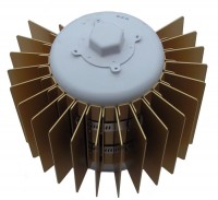
https://www.aircraftspruce.com/cache/20 ... -07394.jpg
anyone using this oil chiller?
anyone using this oil chiller?
Curtis
1950 A model 1256D
1950 A model 1256D
Re: Photos of blast tube placement
How do you know that's a "chiller" (sounds a bit hopeful) and not a heater? It sits downstream of hot cylinders and exhausts. (Might be interesting to sample the air temp in that area during flight, especially climb.)Curtis Brown wrote:https://www.aircraftspruce.com/cache/20 ... -07394.jpg
anyone using this oil chiller?
'53 B-model N146YS SN:25713
50th Anniversary of Flight Model. Winner-Best Original 170B, 100th Anniversary of Flight Convention.
An originality nut (mostly) for the right reasons.
50th Anniversary of Flight Model. Winner-Best Original 170B, 100th Anniversary of Flight Convention.
An originality nut (mostly) for the right reasons.